hunterfan-blog-post
Reverse-engineering a Hunter ceiling fan remote
My ceiling fan came with a hand-held 433 MHz remote that — like most
of them — was starting to die. Hunter sells replacements, but they
won’t show up for a week, and the OEM remote isn’t smart-home friendly
anyway. I wanted the fan in my LCARS smart-home dashboard, which means
an ESP8266 needs to speak the same protocol the OEM remote does.
A few hours with a cheap 433 MHz receiver, and an
oscilloscope was enough to figure out the protocol and build a small
Arduino library that can both learn captured packets and replay
them. The library is up on GitHub: breandan/HunterFan.
This post is a walk-through of what the protocol actually looks like
on the air, why it’s shaped the way it is, and how the library
implements it.
Hardware
- A cheap 433 MHz SYN115 OOK transmitter module on a GPIO.
- A matching SYN480R OOK receiver on an interrupt-capable GPIO.
(Optional — you only need this if you want to capture packets from
the OEM remote.) - Any Arduino-flavored MCU. I’m using an ESP8266, but the library
builds for ESP32 and AVR too.
OOK (“on-off keying”) is the simplest possible RF modulation: you turn
the carrier on for a HIGH bit and off for a LOW bit. The receiver
module hands you a clean digital signal — no demodulation work needed.
What’s left is figuring out the framing on top of that digital
bitstream, which is the interesting part.
The bit clock
Every other timing in this protocol is in multiples of a single bit
clock period. I’ll call it T. By measuring the shortest pulses on
a capture, T comes out at 400 µs — close enough to “400” that the
firmware almost certainly uses it as the configured value.
The library exposes T as a public field, so you can adapt it to other
similar OOK remotes:
HunterFan fan(TX_PIN);
fan.clkUs = 400;   // T, the bit clock
fan.begin();
Bit encoding — PWM in a 3T window
Each data bit takes one 3T window — 1.2 ms total — and the ratio
of HIGH-to-LOW within that window encodes the value:
| Bit | Waveform |
|---|---|
1 |
2T HIGH, then 1T LOW |
0 |
1T HIGH, then 2T LOW |
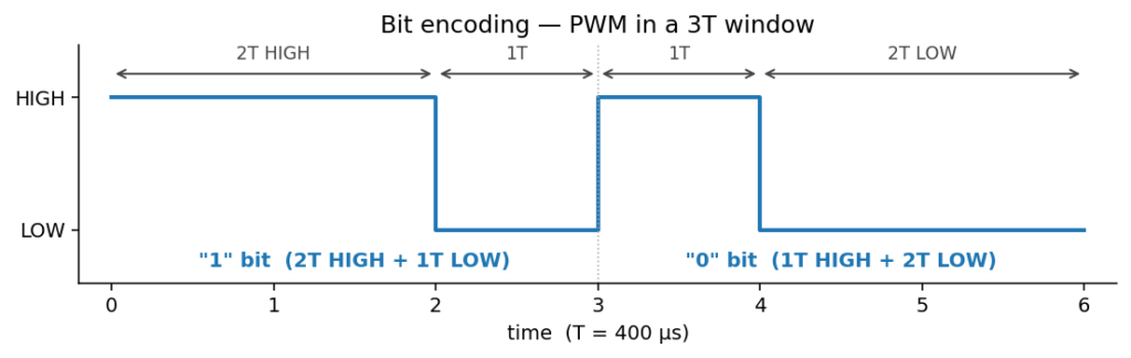

This is pulse-width modulation, but with a twist: the transition
between any two bits is at a known place (the 3T boundary), so you can
recover the clock from the signal itself. Decode is dead simple — for
each 3T window, look at how long the line stayed HIGH. A fun thing about
this is that it means you don’t actually need to listen to the levels at all.
All the information is encoded in the time between transitions, and
whether the edges are falling or rising is irrelevant.
Frame structure
A full transmission has four parts: preamble, anchor gap, data, and
inter-frame gap.
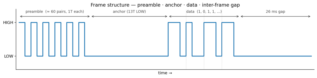

Preamble. About 60 alternating HIGH/LOW pulses, each 1T wide. This
is purely for the receiver’s automatic gain control to settle. Cheap
OOK receivers have a slow AGC loop and need a steady stream of edges
to find their bias point before they can reliably distinguish 0s from
1s — the preamble is the OEM’s way of making sure that’s stable before
the actual data starts.
Anchor gap. A single LOW period of 13T (~5.2 ms) that marks
the boundary between preamble and data. Because the preamble is at 1T
and the longest in-band pulse during data is 2T, this 13T gap is
unmistakable — a perfect framing token.
Data. 65 or 66 PWM-encoded bits.
That’s enough to pack a device-ID, a button code, and a checksum.
Inter-frame gap. ~26 ms of silence between frames.
Repeats — fault tolerance the easy way
RF in the 433 MHz ISM band is noisy. Every garage door opener,
weather sensor, doorbell, and tire-pressure monitor in your
neighborhood is also splattering OOK in this range. To deal with that,
the OEM remote transmits every packet three times with a 26 ms gap
between repeats:

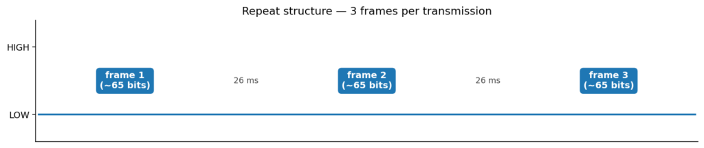
A receiver that catches any one of the three frames cleanly is
enough. The library transmits with repeats = 3 to match the OEM,
but you can crank it up if your reception is dodgy.
What a real command looks like
Here’s the first byte of a captured “light toggle” command — 0xA6,
sent MSB-first on the wire so it reads as 1010 0110 left-to-right:

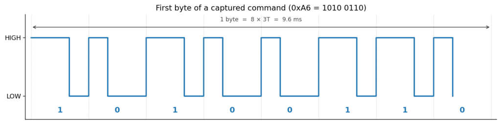
You can read each bit straight off the trace by the width of the HIGH
pulse — wide pulse = 1, narrow pulse = 0. The full command is 66 bits,
so this image is just the first 9.6 ms of it.
The bit-reversal quirk
One detail that’s easy to get wrong: the protocol transmits each byte
MSB-first, but most bit-manipulation code in C is naturally LSB-first
(bit 0 is the low bit of byte 0). The library handles this by
bit-reversing each byte on the way in and out, so the hex string
you pass to sendHex() matches what a logic analyzer would display
(left-to-right, MSB first), but the internal storage is in the
LSB-first order that _getBit/_setBit want:
out[n++] = _reverseBits((uint8_t)((hi << 4) | lo));It’s a small thing, but it’s the difference between “transmit a
captured packet and see it work” and “transmit a packet and watch
nothing happen because the fan got 0x65 instead of 0xA6”.
A few of my captured commands
| Button | Hex (66 bits) |
|---|---|
| fan | A6FF346CBB011FEE00 |
| up | A6FF346CBB100EFF00 |
| down | A6FF346CBB1016FE80 |
| light | A6FF346CBB18067F80 |
You can see the shared prefix A6FF346CBB is presumably the remote’s
device ID (paired to my fan), and the last few bytes are the command
- checksum. Hunter doesn’t publish the checksum algorithm, but for
my fan it doesn’t matter — I’m replaying captured packets verbatim,
not synthesizing new ones, so I just need to faithfully reproduce the
bits I recorded.
Using the library
Two examples — capture and replay:
#include <HunterFan.h>

HunterFan fan(/* txPin */ 12, /* rxPin */ 13);

void setup() {
    Serial.begin(115200);
    fan.begin();
}

void loop() {
    uint8_t buf[16];
    uint8_t bits;
    if (fan.receive(buf, sizeof(buf), bits, /* timeoutMs */ 5000)) {
        Serial.printf("Got %u bits: %sn",
                      bits, HunterFan::toHex(buf, (bits + 7) / 8));
    }
}
#include <HunterFan.h>
HunterFan fan(/* txPin */ 12);
void setup() {
fan.begin();
fan.sendHex("A6FF346CBB18067F80", 66); // toggle the light
}
void loop() {}The toHex output and sendHex input share a format, so a capture
round-trips verbatim.
Timing on the ESP8266 — one small surprise
The ESP8266’s WiFi stack runs in an interrupt context, and any ISR
during a transmit can shift a HIGH or LOW pulse by tens of µs. That’s
not enough to break the receiver — the library’s ±45 µs tolerance
absorbs it — but if you really want clean transmits you can set:
fan.disableInterruptsDuringTx = true;…on ESP8266 and ESP32. Don’t set it on AVR though: disabling
interrupts there kills the Timer0 overflow that micros() depends on,
and you’ll hang inside _waitForNextClock() after about 2 ms.
The transmit routines and ISR handler are tagged with
ICACHE_RAM_ATTR / IRAM_ATTR so the code lives in IRAM and isn’t
subject to flash-cache stalls — another source of timing jitter if you
forget to do it.
What I’d do differently
- Add a checksum solver. Right now I can only replay captured
packets. If you wanted to synthesize a command you hadn’t recorded
from a paired remote, you’d need to reverse Hunter’s checksum. Most
of these protocols use a CRC-8 or XOR-fold of the device-ID +
command — a weekend project for a future me. - Non-blocking receive.
receive()blocks until it gets a packet
or the timeout fires. For a one-shot “learn this button” UI that’s
fine, but if you want a long-running listener you’d want a
callback-driven API instead.
Source
Library + examples: https://github.com/breandan/HunterFan
MIT licensed — drop it into your libraries/ folder and have at it.
Leave a Reply